1. Feeding Section (Feeding Device)
Common types currently in use include: drum feeders, combined feeders, chute feeders (feeding trolleys), and screw feeders.
① Drum Feeder
The drum feeder resembles a drum open at both ends and features internal spiral components for conveying ore. As the feeder rotates along with the ball mill, the ore is transported into the mill following the spiral path. Drum feeders are suitable for feeding dry materials into the ball mill.
② Combined Feeder
The housing of the combined feeder features an inlet and an outlet on its front and rear side plates, respectively. It is characterized by an internal partition plate that divides the housing cavity into an inlet chamber and a guide chamber. Feed-through holes are distributed along the periphery of the partition plate, while a cylinder is positioned at the center of the guide chamber, with its axis aligned with the outlet. A spiral guide plate is installed between the central cylinder and the housing within the guide chamber, and material-transfer openings are provided on the cylinder wall on the inner side of the spiral guide plate. This ingenious and rational design allows for the intake of larger lump materials and maintains a high material level within the mill. It prevents material backflow or spillage, reduces labor intensity, avoids pollution, increases feed capacity, and enhances productivity and profitability. It can handle both dry ore and wet materials (such as classifier underflow/sand returns) and is frequently used in the first stage of closed-circuit grinding. Additionally, because the combined feeder facilitates the addition of steel balls into the ball mill, it is also utilized in second-stage grinding circuits. Overall, the combined feeder is widely applied.
3) Screw Feeding Device
The screw feeding device is a common feeding method for dry mills and wet grinding mills. It primarily consists of an enclosed screw feeder, a hopper, and a support structure. Equipped with a motorized drive unit, it functions as an active (powered) feeding system. ④ Chute-type feeding device
The chute-type feeding device is a common feeding method for large-scale mills, characterized by its simple structure and ease of replacement. It primarily consists of an inclined pipe, a sealing assembly, a hopper, and a support mechanism; the support mechanism is sometimes designed as a movable trolley to facilitate inspection and maintenance.
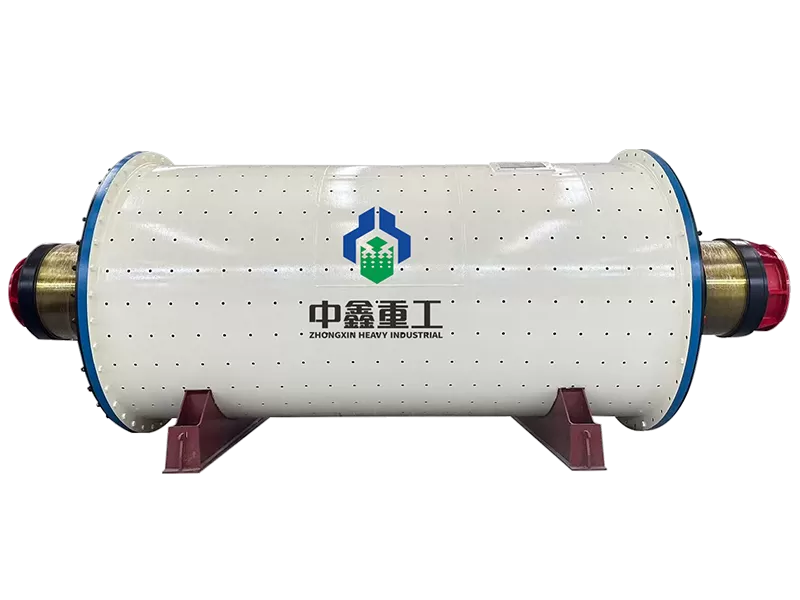
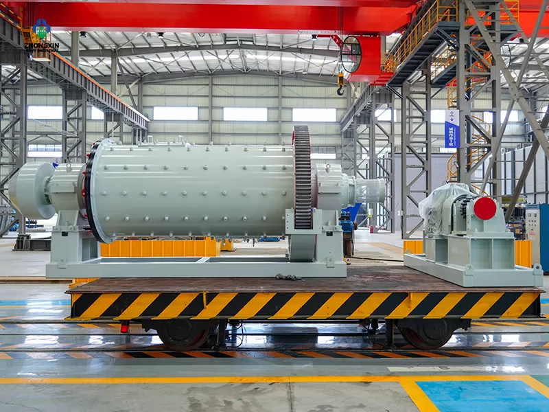
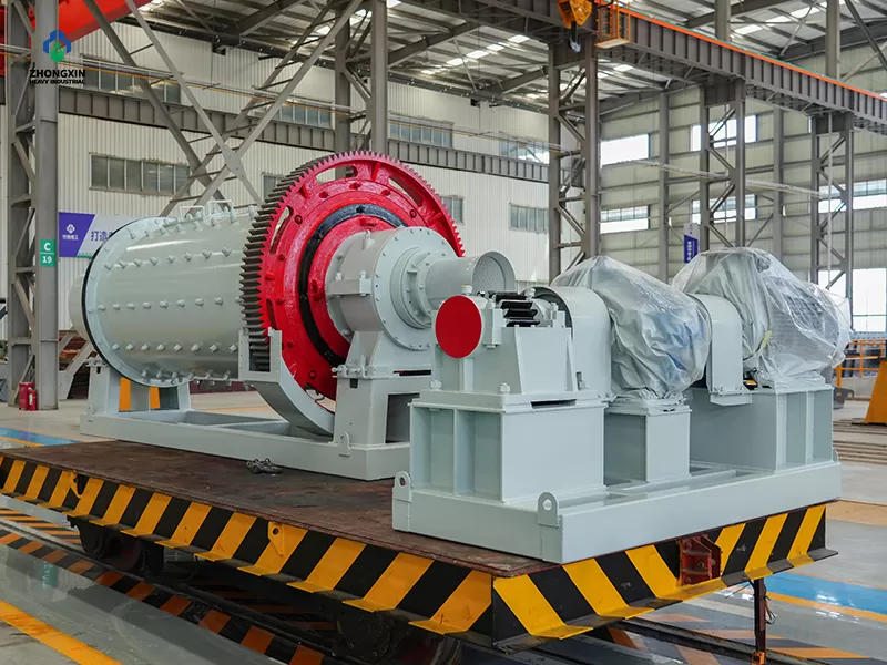
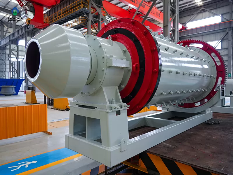
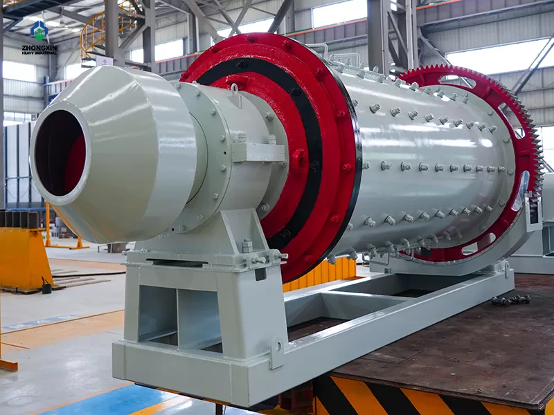
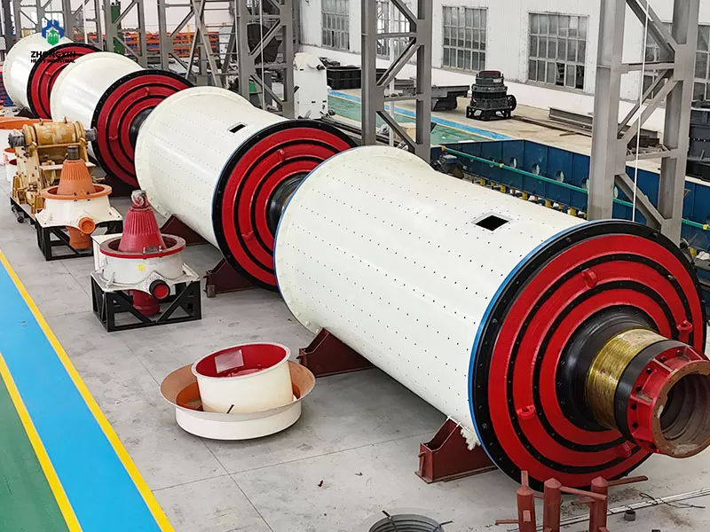
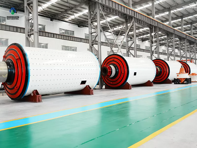
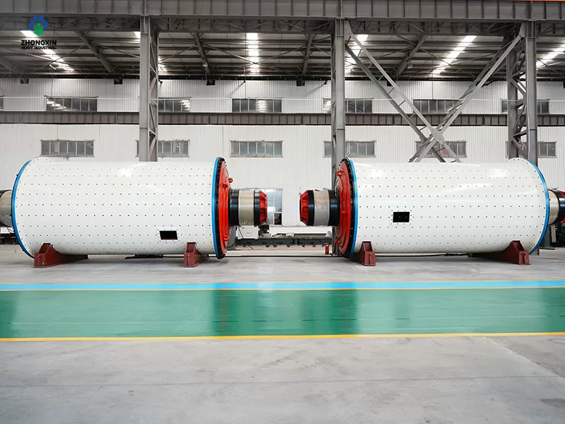
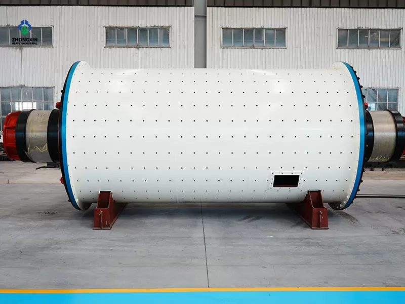
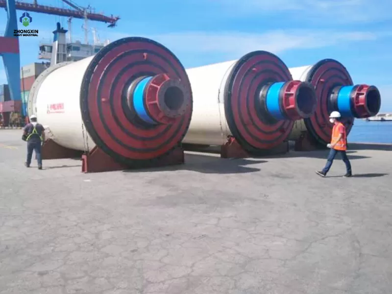
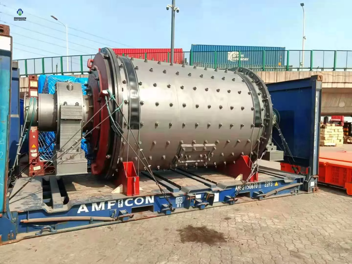
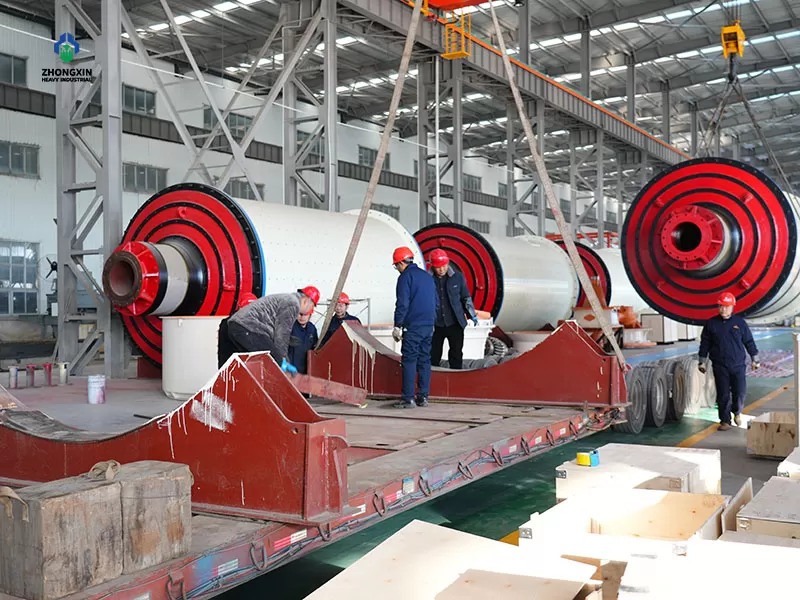
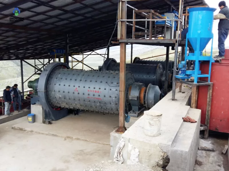
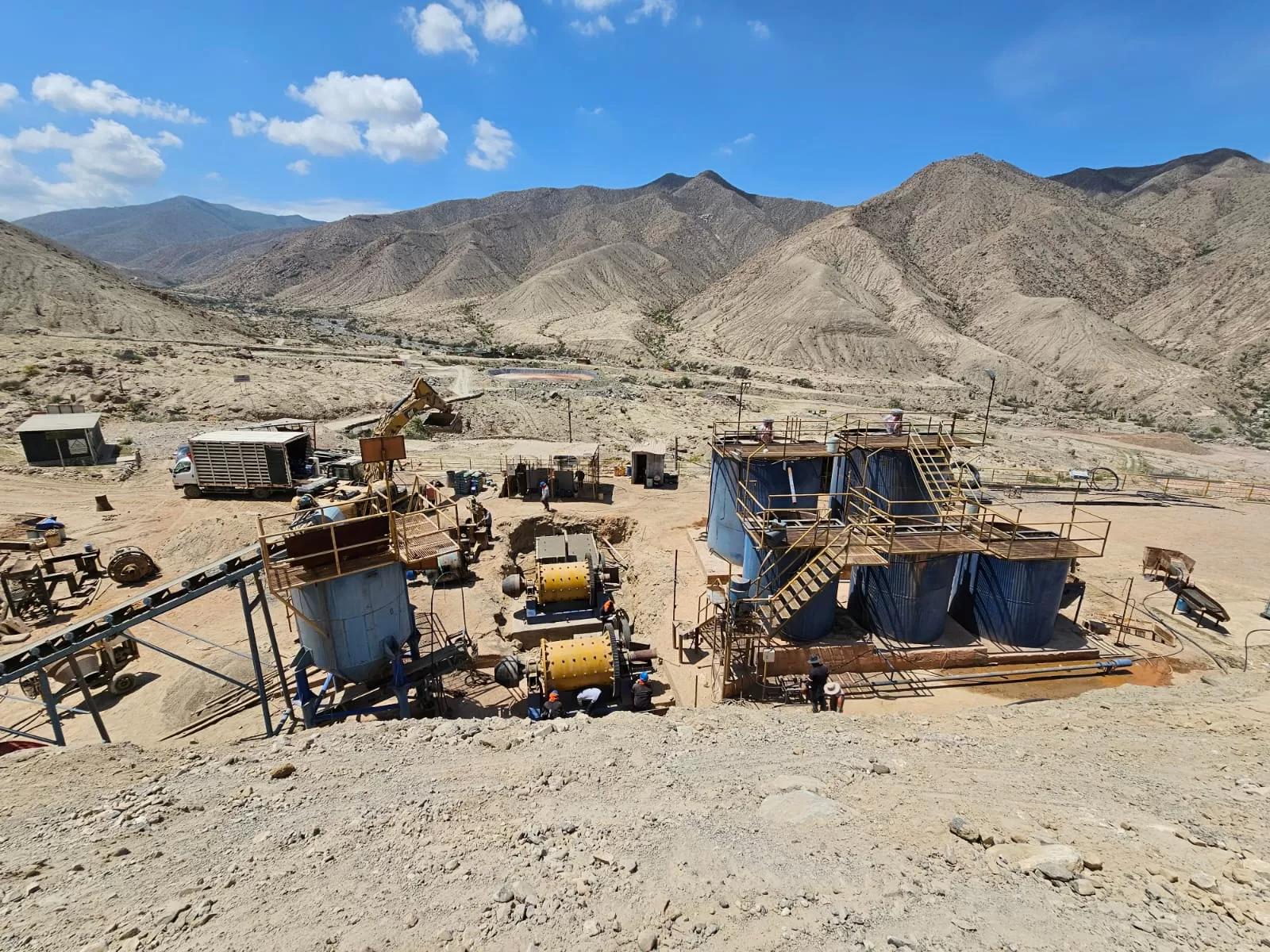
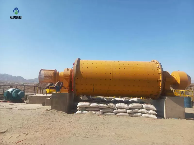
2. Feeding section: Composed of the feed end cover, end liner, and feed bushing.
3. Shell section: Composed of the shell (fabricated by welding flanges to a rolled steel plate cylinder) and shell liners; the shell is equipped with one or two manholes for liner replacement.
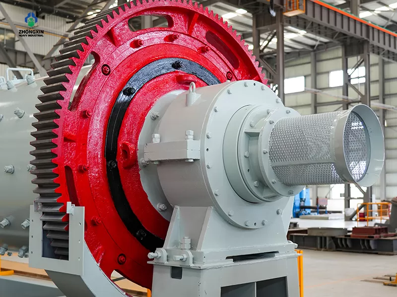
4. Discharge section: Available in overflow and grate types. The overflow type consists of the discharge end cover, end liner, and discharge bushing; the grate type consists of the discharge end cover, discharge grate plate, inner liner, and discharge bushing. A cylindrical discharge screen is sometimes added to the discharge section.
5. Support section (also known as the main bearing section): Features either rolling bearings (typically spherical roller bearings) or sliding bearings.
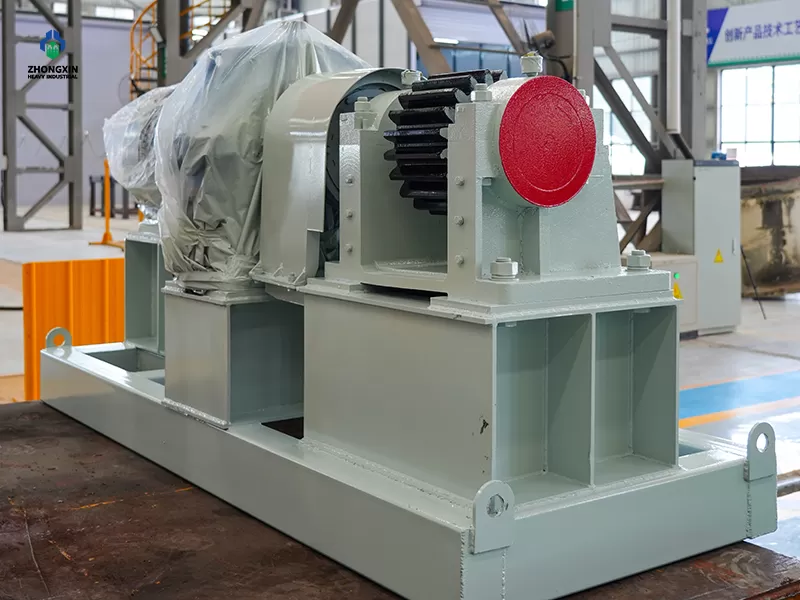
6. Drive section:
① Asynchronous motor drive: The motor drives the speed reducer via a coupling; the low-speed shaft of the reducer then drives the pinion gear via a coupling, which in turn drives the large gear.
② Synchronous motor drive: The motor drives the pinion gear via a clutch, which in turn drives the large gear.
7. Slow-speed drive device: Composed of a motor, brake, high-ratio speed reducer, helical-tooth clutch, etc.
8. Shell lifting device: Composed of a lifting bracket, a jack, and a support stand.
9. Lubrication system: Divided into grease lubrication and circulating oil (fluid oil) lubrication types.
10. Cooling system
11. Foundation
12. Electrical control system
 WhatsApp
 WeChat